Learn about
Our technology
What’s the difference?
We started to develop a new generation of power distribution units because we realized that the entertainment industry technology has changed a lot over the last couple of years. The move to LED and video fixtures creates a lot of new possibilities but also new challenges.
Power distribution to a large number of complex loads such as switch-mode power-supplies, quickly altering loads and rapidly changing conditions for dynamic setups creates the need for new solutions and technology.
Why should you get a power-distro from Stage Smarts? Here we try to answer that question and explain why we do the things we do.
Contents
Hydraulic-magnetic RCBO’s
The standard breaker being used in power distribution is the thermal-magnetic breaker. This type of breaker works fine under the normal conditions that can be expected in for example a permanent installation in a residential building or similar. However, when used together with the complex loads and circumstances encountered in the entertainment and event industry things become a bit different.
The design of the thermal-magnetic breaker relies on a bimetallic strip much like the ones used in thermostats to trip the breaker. When an overload occurs, the strip heats up, bends and eventually reaches a mechanism that trips the breaker. This design has some problems that will affect your distro to work reliably under conditions that are to be expected in a show or event environment.
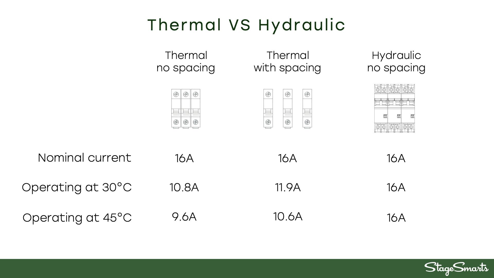
- Breaker rating goes down as temperature goes up.
- Breaker need to cool down before reset is possible.
- Close proximity breakers heat each other and degrades performance.
- Peak and inrush current causes the breaker to prematurely trip.
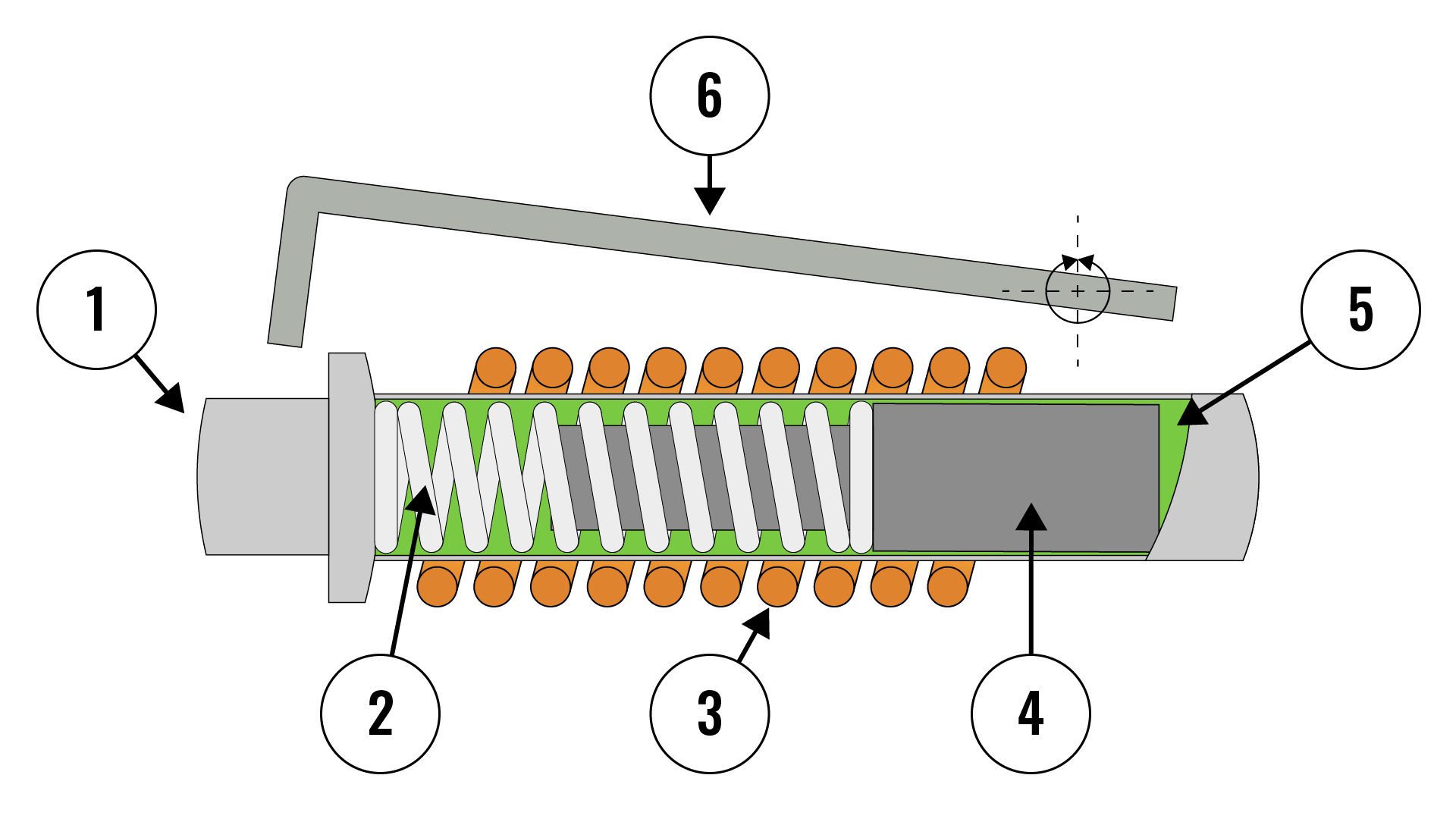
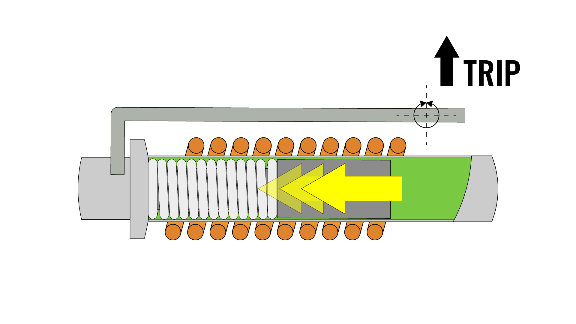
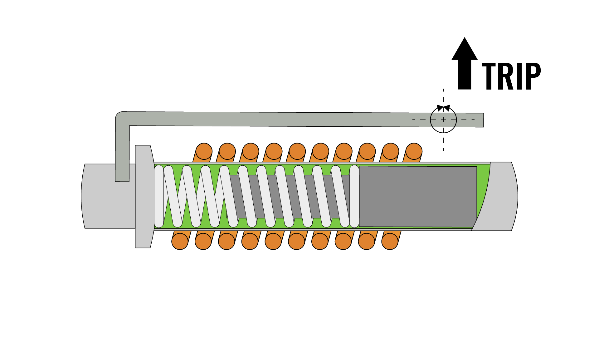
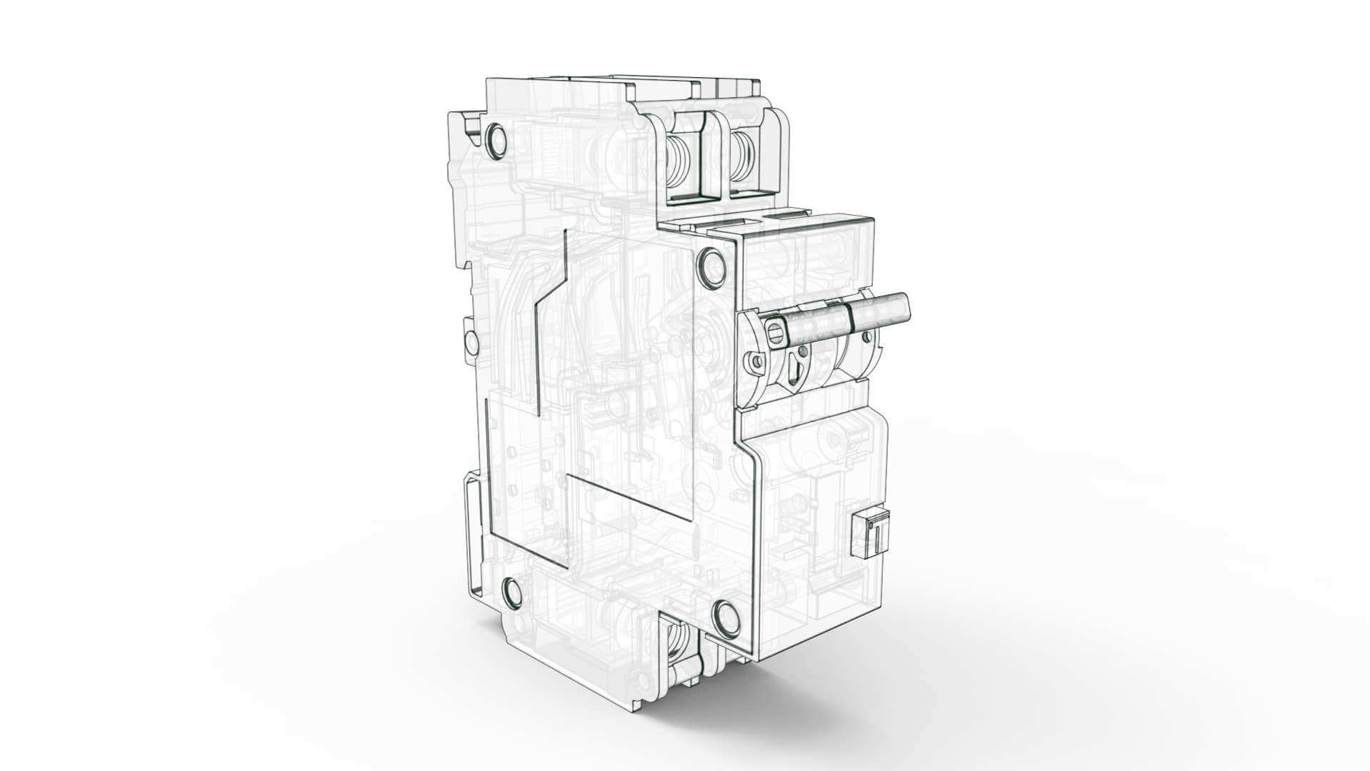
The hydraulic-magnetic breaker solves these problems with an advanced and more reliable design. The trip-function in the hydraulic-magnetic breakers are comprised of a spring-loaded core inside a sealed and fluid-filled tube. The tube is mounted in the center of an electric coil that conducts the current thru the breaker, when the current raises the core starts to move thru the tube and when it reaches the opposite side the breaker trips. The characteristic of the breaker can be very precisely defined by altering the fluid viscosity and the spring counterforce. The breaker will keep its rated performance over a wide temperature range since the fluid viscosity stay the same regardless of temperature.
If the current overloads the circuit breaker (load above the rated current), the magnetic flux in the solenoid produces sufficient pull on the core to start it moving towards the pole piece. The dampening fluid creates a time delay to enable the breaker to resist short term peaks created by startup inrush currents, motors or similar. When the overload disappears, the spring returns the core to normal position. Should the overload persist the core reaches the pole piece and the breaker trips.
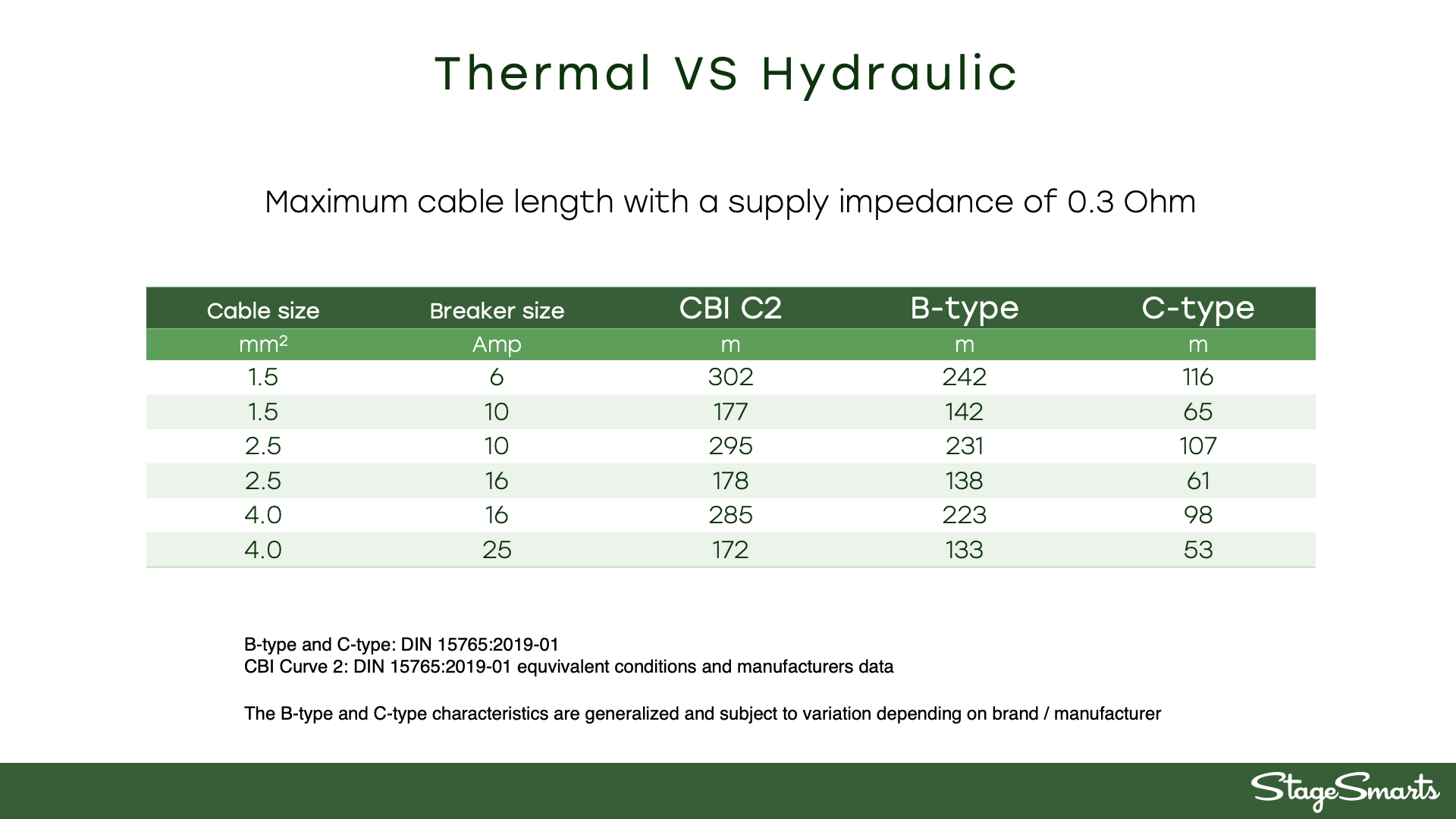
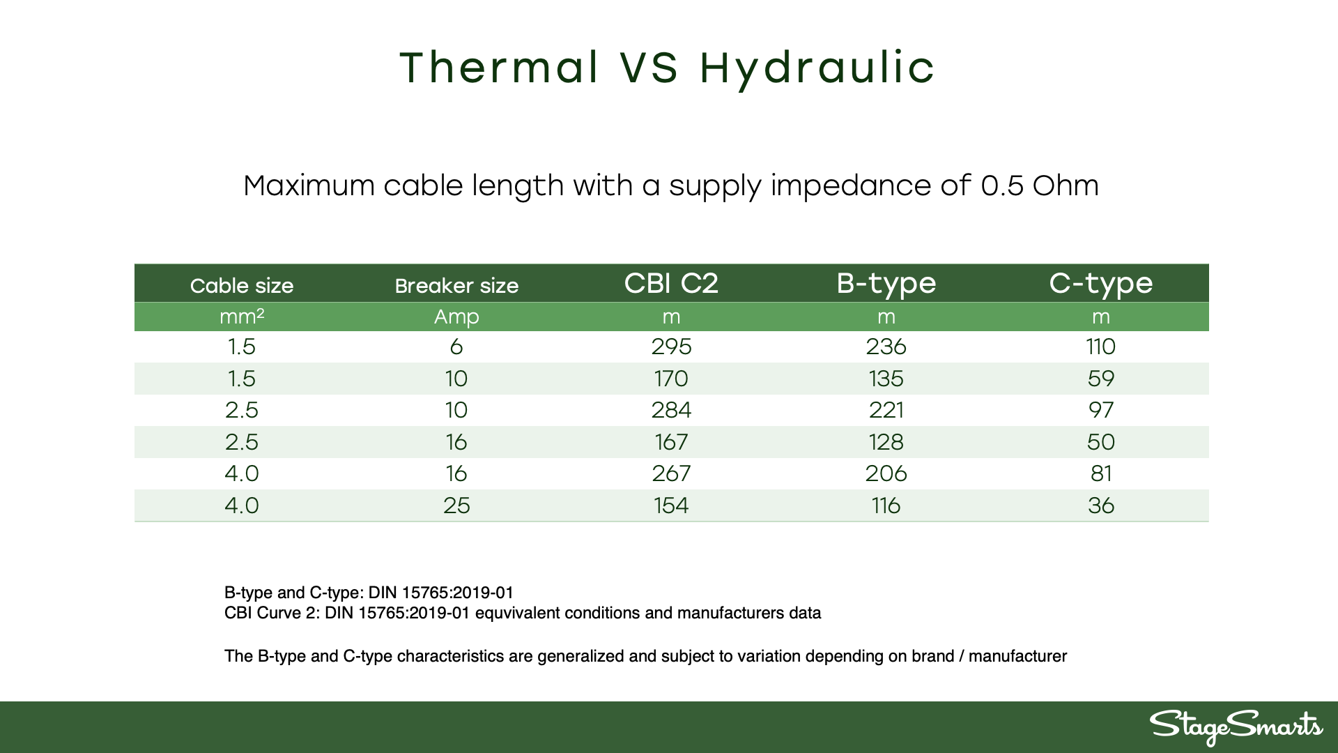
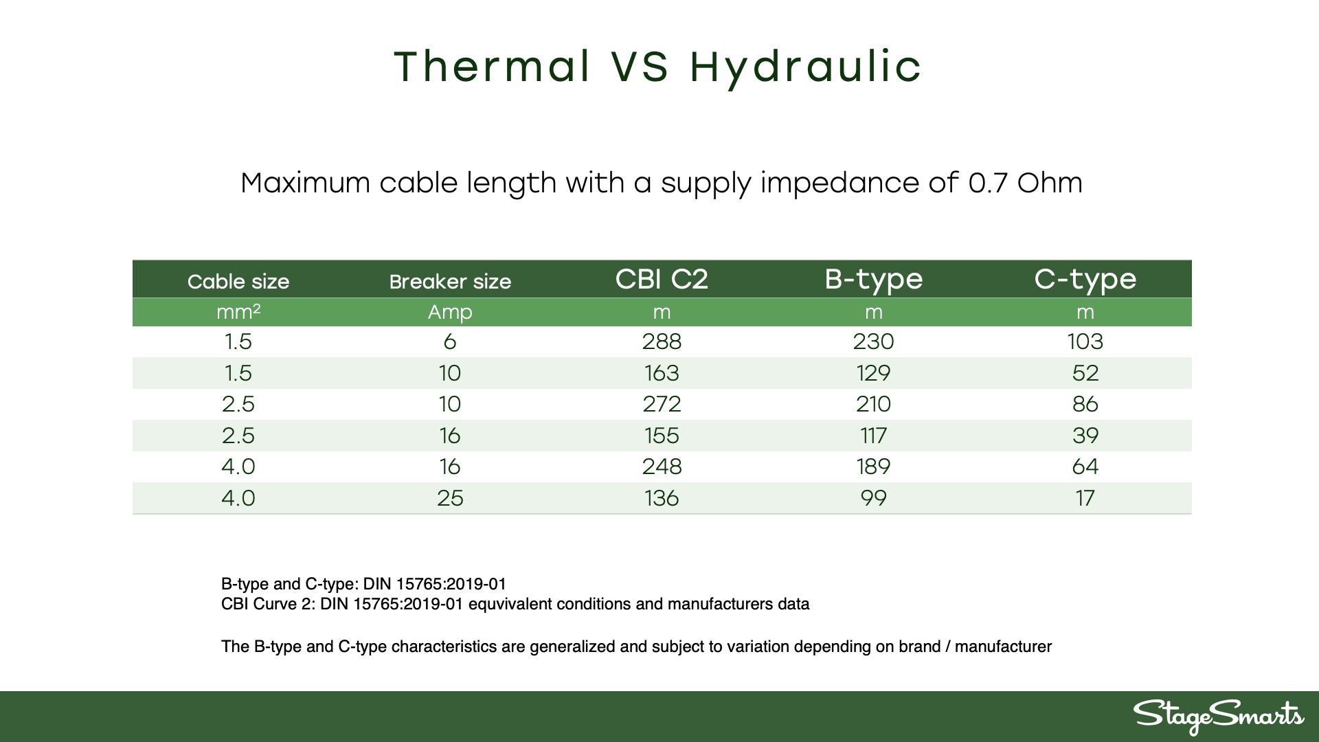
The hydraulic-magnetic design enables the breaker to be unaffected by ambient temperatures and maintain the required disconnection time even when connected to long cable runs. This makes for quite a big difference in the normal day to day use as we can see in the images below.
Residual-current circuit breaker with overcurrent protection (RCBO)
The biggest causes of “nuisance tripping” in power distribution for the entertainment industry are caused by earth leakage and inrush currents.
Earth leakage are mainly caused by the filtering of the mains in switch-mode power supplies and long cables from the breaker to the connected load. The combined leakage currents on a single circuit can quickly reach above the required 30mA protection, causing the residual-current protection to trip long before the maximum rated breaker current is reached. To further complicate matters the residual-current protection on most breakers and RCDs engage around 20mA and can even trip as early as 15mA in bad cases, leaving you with very little usable load on each circuit.
Inrush currents are short-term currents several magnitudes higher than normal current draw. Switch-mode power supplies creates these currents when energized or when the connected load quickly raises from low consumption to high. Turning on a large LED-video wall with lots of power-supplies are a prime example of this.
We design our products to counter these problems by using breakers with integrated residual-current protection on each and every channel for maximum selectivity and minimal summation of leakage currents. Furthermore, the RCBOs we use have very tight tolerances for the residual-current protection and normally operates in the 23-30mA range giving you a lot more headroom to connect more equipment on each circuit.
The hydraulic-magnetic design can handle inrush-currents and peaks much better then thermal-magnetic designs since the dampening fluid “evens-out” these peaks and there is no thermal build-up causing the breaker to fatigue over time.
Hydraulic-magnetic RCBO advantages.
- 100% load capacity at any temperature (-40°C to +85°C).
- Direct reset possible – no cooling time necessary.
- Tripped breaker indicated (handle in mid-position).
- Handles inrush currents better.
- Drives longer cabling (2-3 times longer than “C” type).
- 50% more leakage-current headroom (23-30mA).
- Built to EN 60947-2 standard (industrial grade).
- Sealed against dust and humidity.
- 2-pole (a requirement in many countries).
Loss of neutral protection
A disconnected or failing neutral connection in a 3-phase system will almost always lead to catastrophic failure, damaged equipment and as a consequence a lost or crippled show.
The neutral acts as a balancing point for the phases and keeps the voltages stable under all load conditions. If the neutral fails, overvoltage on some of the phases will likely destroy the connected equipment very quickly. The importance of a good and reliable neutral connection can’t bet overstated, but in reality, many people just assume it will work as expected. In the world of entertainment and events were large amounts of electric power often are arranged as a temporary solution the risks of a bad neutral are a very real threat.
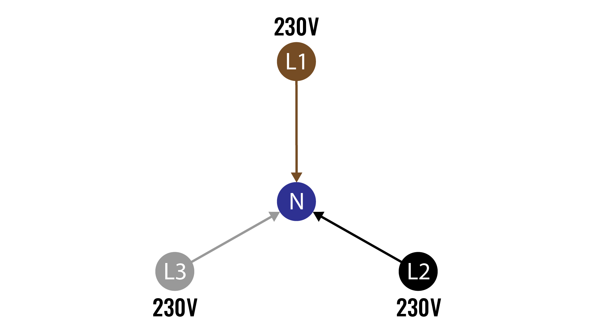
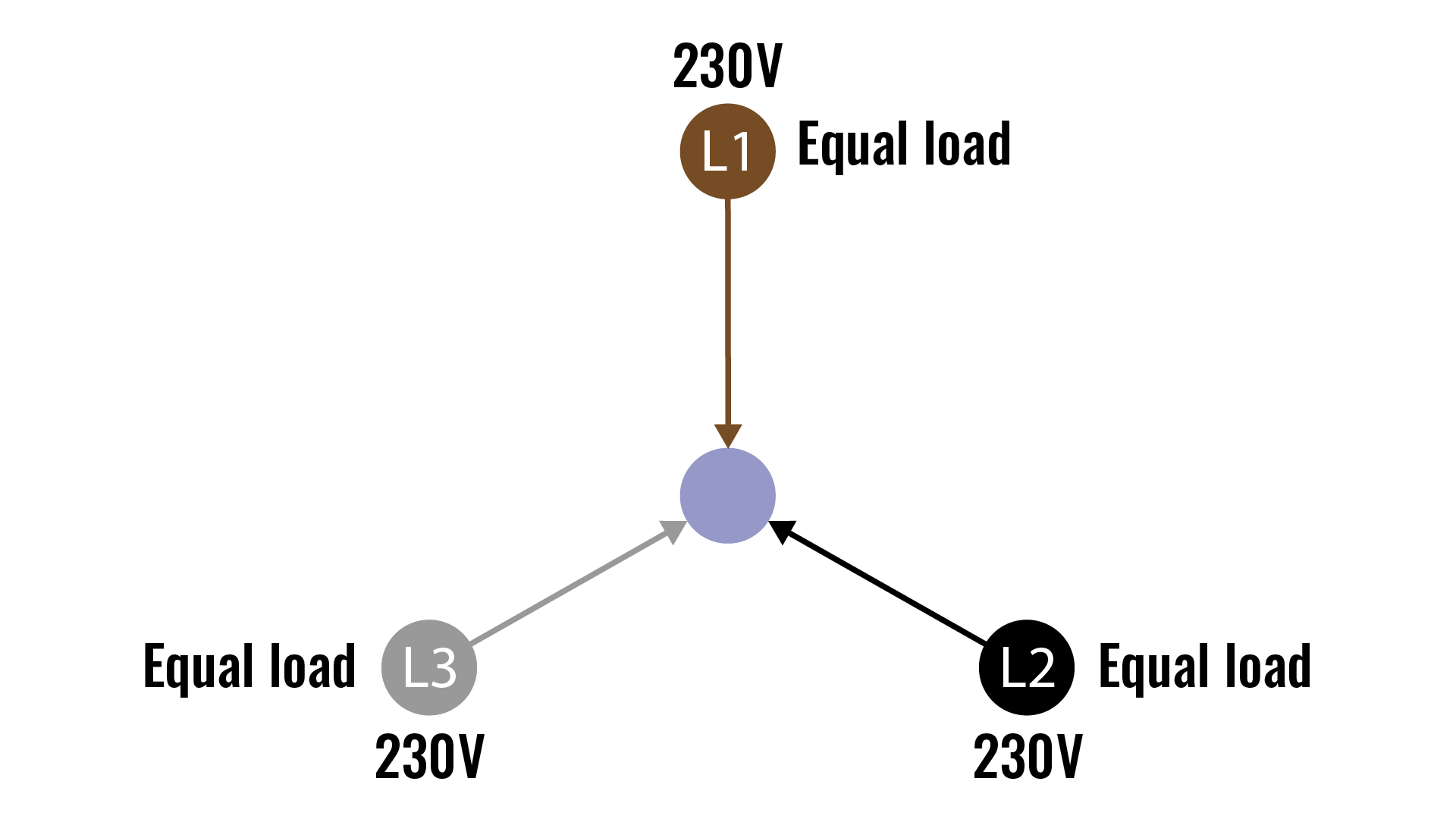
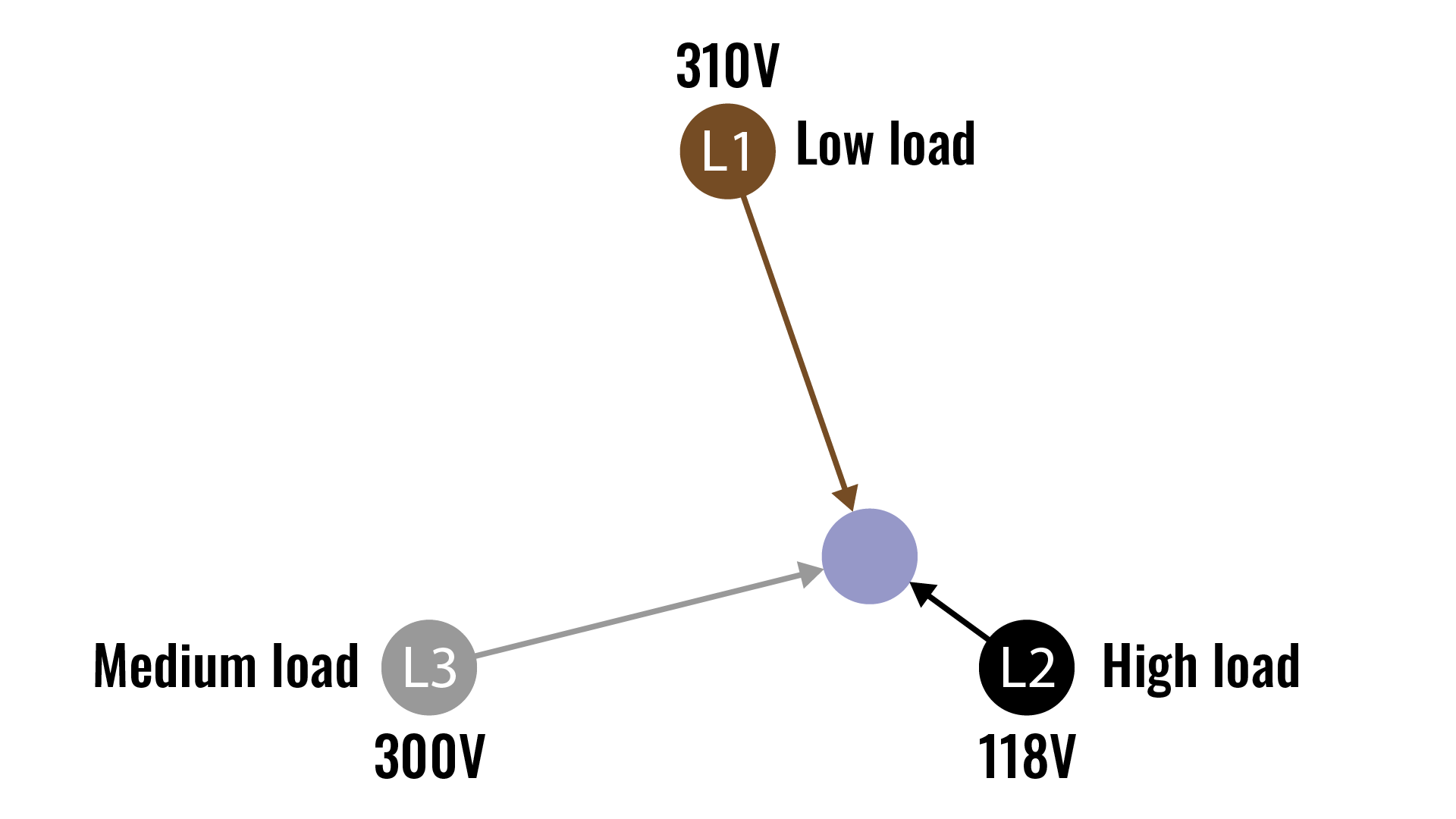
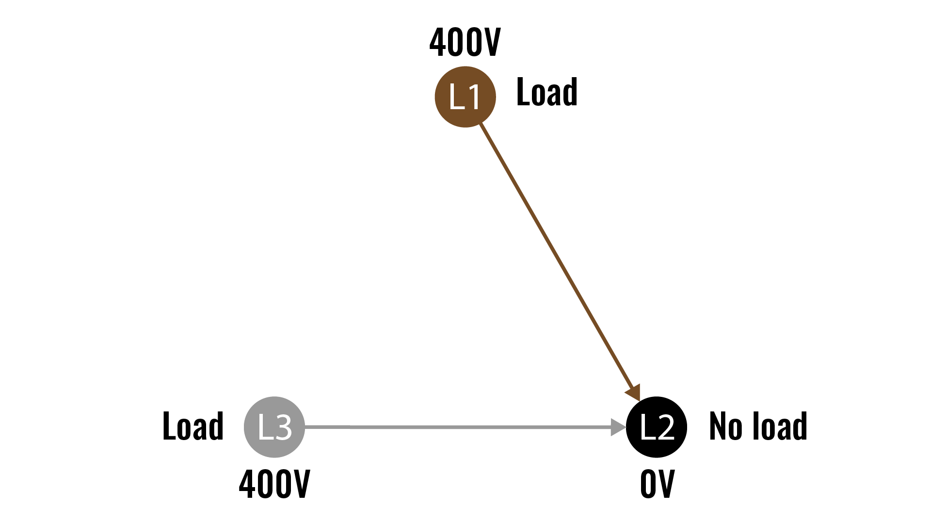
The consequences of a lost or weak neutral connection in a 3-phase system can be a bit difficult to understand so please have a look at the sequence below.
Under normal conditions the neutral conductor balances the phases so that the voltages stay stable even if the load is unevenly dispersed between the different phases.
If the neutral connection is lost due to a poor connection or a faulty conductor a floating neutral point is created between the phases, as long as the load on each phase is equal the voltages will remain the same as the system is in balance. A 3-phase electrical motor for example doesn’t need a neutral connection since the load on all phases always stays the same.
When the load starts to differ between the phases the floating neutral point compensates by drifting towards the phase with the lowest load. This results in a voltage drop on that phase and a voltage increase on the other phases, the phase with the lowest load will receive the highest voltage and the phase with the highest load will receive the lowest voltage.
If the voltages raise high enough the connected equipment will start to fail and severe damages to internal components will occur. As the connected equipment breaks, they no longer present a load to the phase resulting in an even bigger difference between the phases which drives the voltages even higher. The resulting avalanche of damaged gear will drive the floating neutral all the way to one phase that now becomes the “neutral” of the system and the other phases will receive massive overvoltage that few connected things will survive
Protect your equipment
We design our products with maximum safety in mind and we believe that the protecting your gear from catastrophic overvoltage is a big part of that. Stage Smarts has developed a proprietary loss of neutral protection that disconnects the unit from the main supply in an instant if the voltages reach critical values. The system constantly monitors the voltage and has zero start-up time, so your connected equipment is protected from the moment you turn the distribution unit on.
As no system is 100% fail proof, we strongly recommended that you check your power supply BEFORE turning everything on if there is any uncertainty about the quality of the connections. The main meters on all our products are connected before the main breaker so that you can get a reading on all voltages and the frequency without putting the connected equipment at risk. The main meters in our products are protected against overvoltage and will survive even if the power supply is failing.
Remember to always:
- Keep your gear in order.
- Open and inspect crucial wires and connectors at regular intervals.
- Check supply voltages before connecting loads.
- Protect your cables from getting run over.
- Use proper gauge supply cables, especially for the neutral.
Load monitoring
Knowing what’s going on in your setup helps you quickly find errors and take precautions to avoid embarrassing problems, expensive downtime or even a cancelled show. A breaker won’t give you any warning if an overload occurs and the power consumption on each channel can be hard to calculate since the current draw for a connected unit in reality rarely is what’s printed on the label.
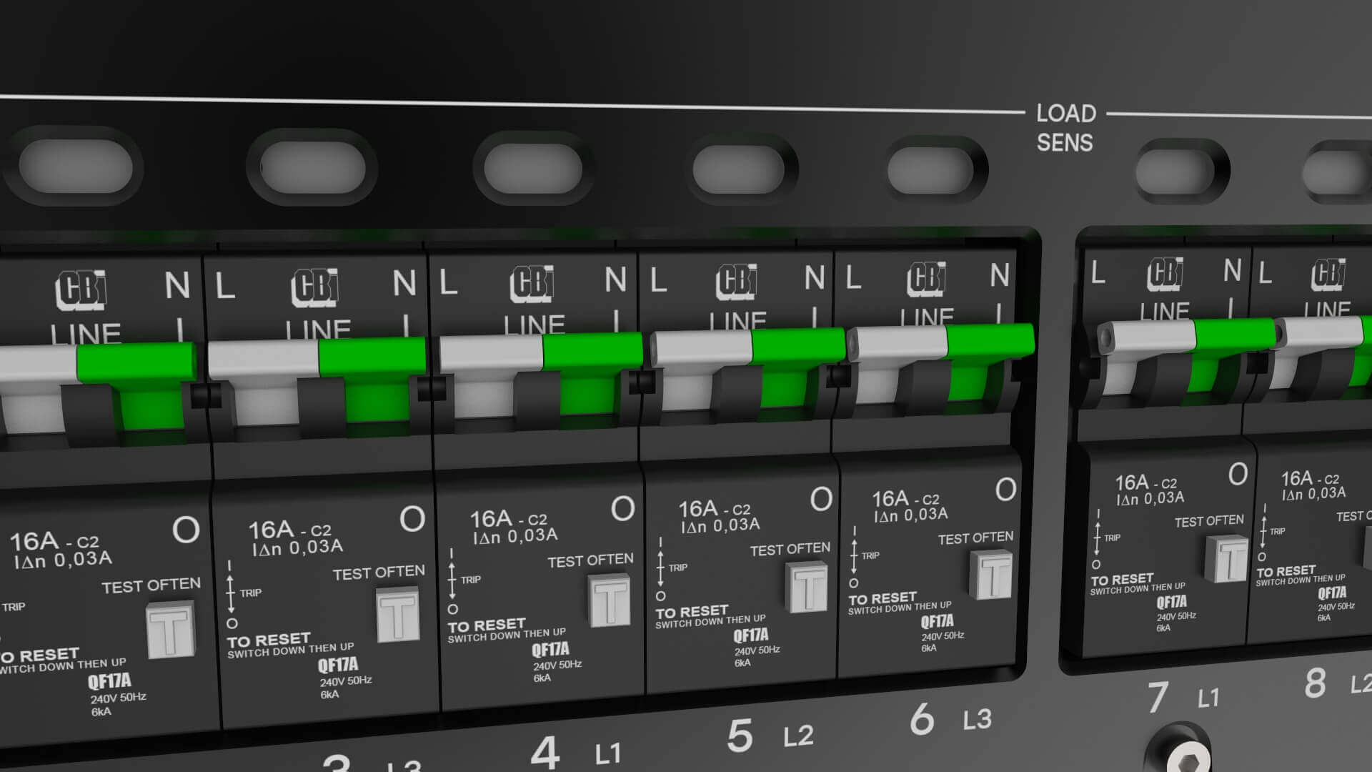
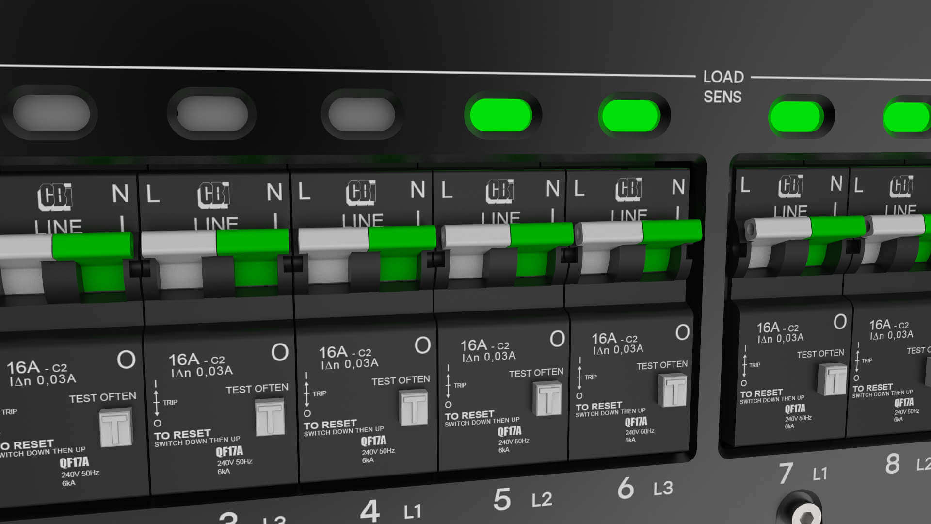
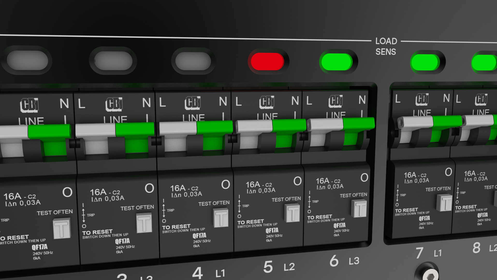
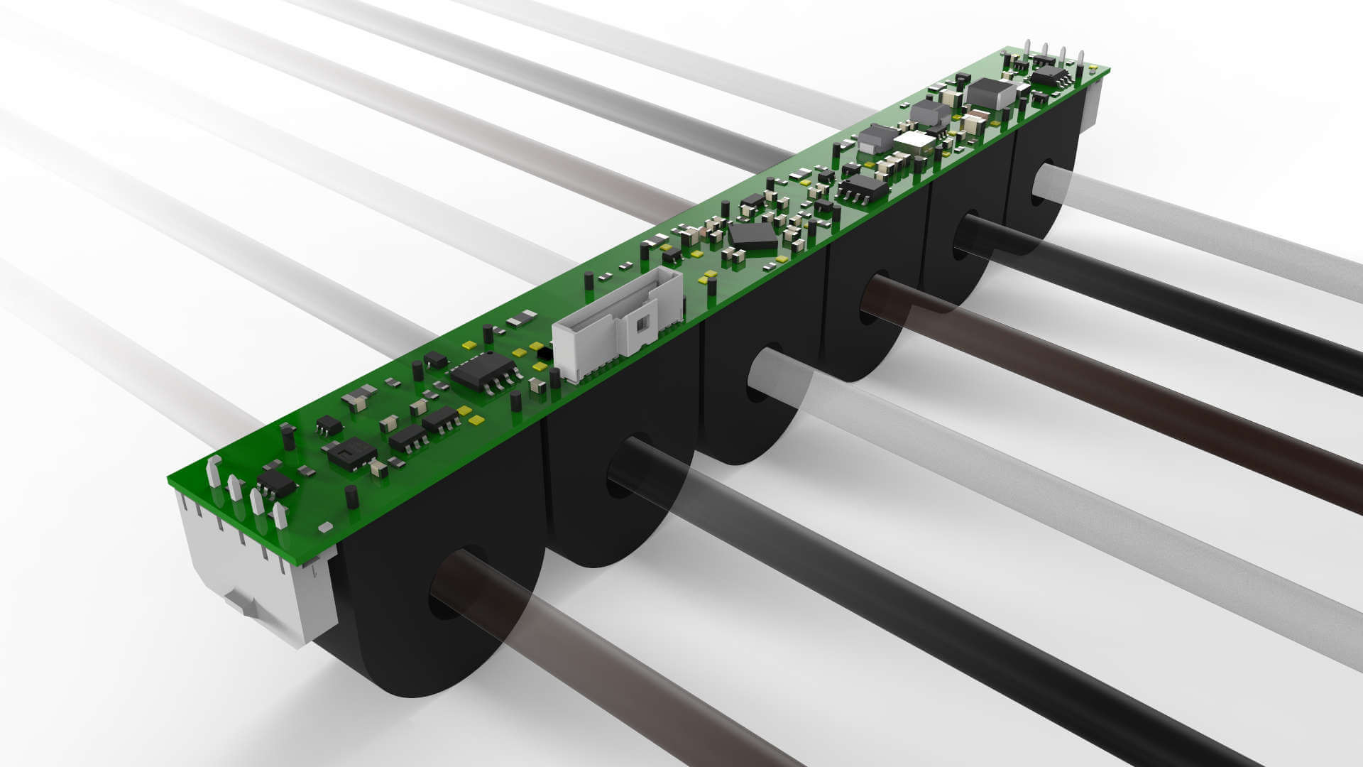
We have developed a unique system that enables you to keep track on the load for all main channels in real time. This enables you to see exactly how your system performs at any given time on any given channel. Our system uses proprietary load sensors that sample the current on each channel and then perform DSP analysis of the data for a true RMS value. Channel load status are continuously updated on the front panel indicators and also sent to the onboard remote supervision system.
When the connected load reaches above approximately 5W the LED indicator turns green to indicate that a load is present on that channel.
Main metering
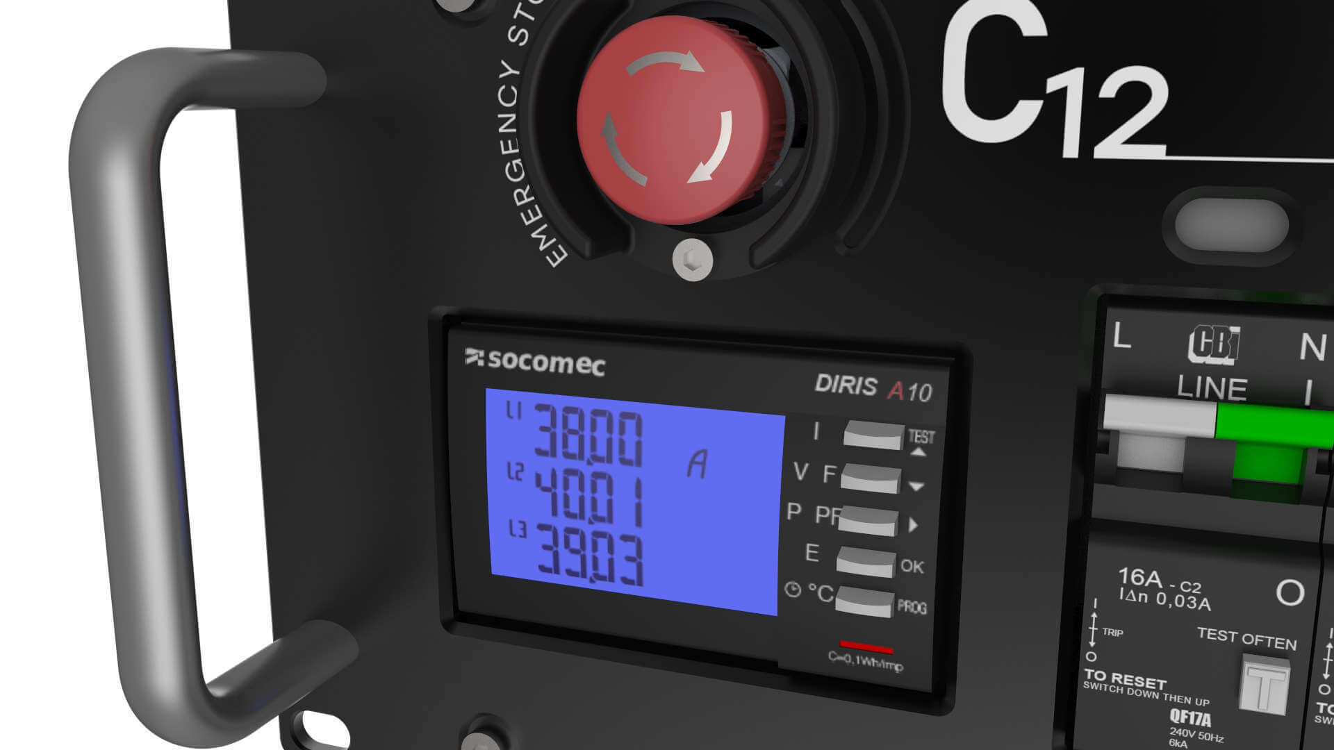
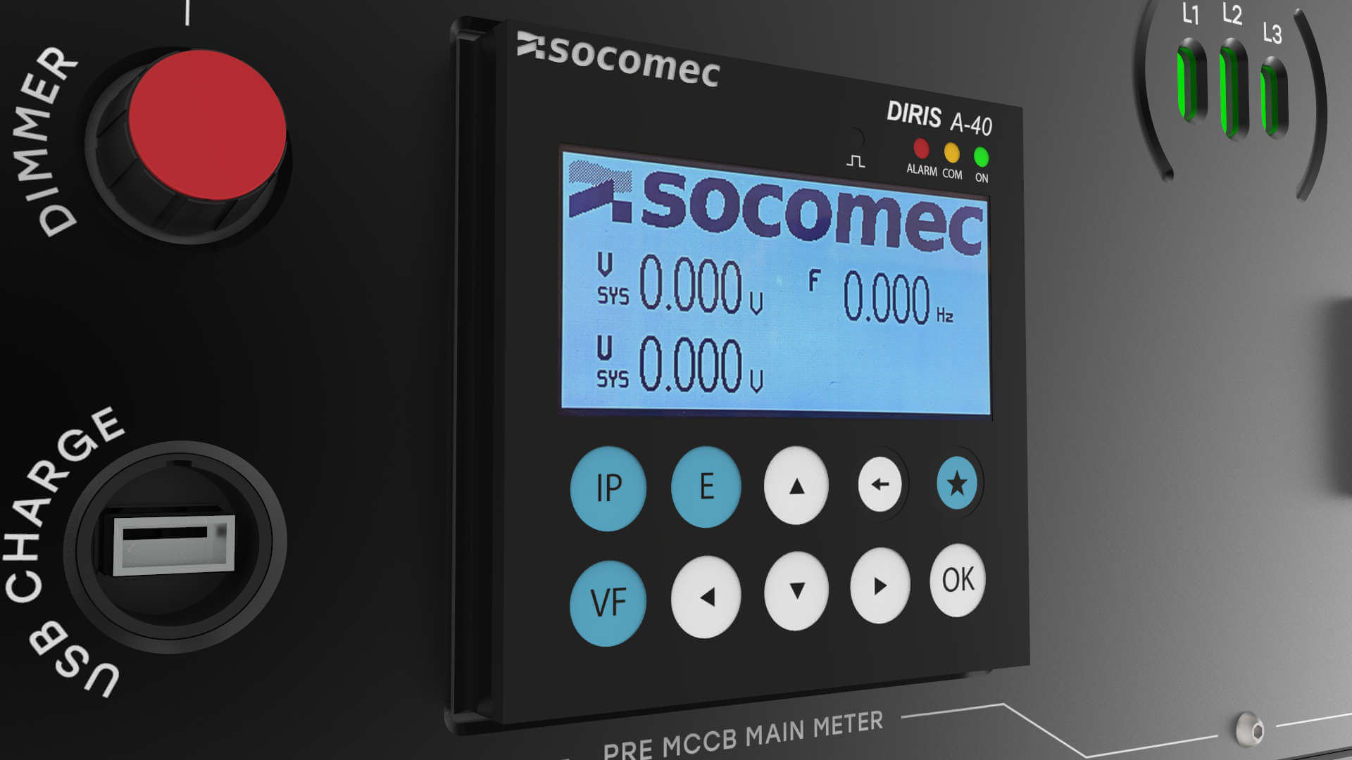
In addition to monitoring all channels on our power distribution units we also have a comprehensive main meter on board so that you can get a good view on the status of the voltage, total load, frequency and more.
We always connect our main meters before the main breaker on the unit, this enables you to check that all supply voltages are correct even before turning the unit on. The main meter are protected from overvoltage by a step-down transformer that lowers the incoming supply voltage to a safe level even if the voltage should reach around 400V. This means that you will be able to get an accurate reading even if there is something terribly wrong with the supply.
The data collected by the main meter is also sent to the remote supervision system.
The meter will provide you with the following data:
- Current – instantaneous and maximum average: L1, L2, L3, N
- Voltage L1-N, L2-N, L3-N, L1-L2, L2-L3, L3-L1
- Power – instantaneous: 3P, ΣP,3Q, ΣQ, 3S, ΣS
- Power – maximum average: ΣP, ΣQ, ΣS
- Power factor – instantaneous: 3PF, ΣPF
- Metering of active and reactive energy
- Harmonic analysis
- Internal temperature
Remote supervision
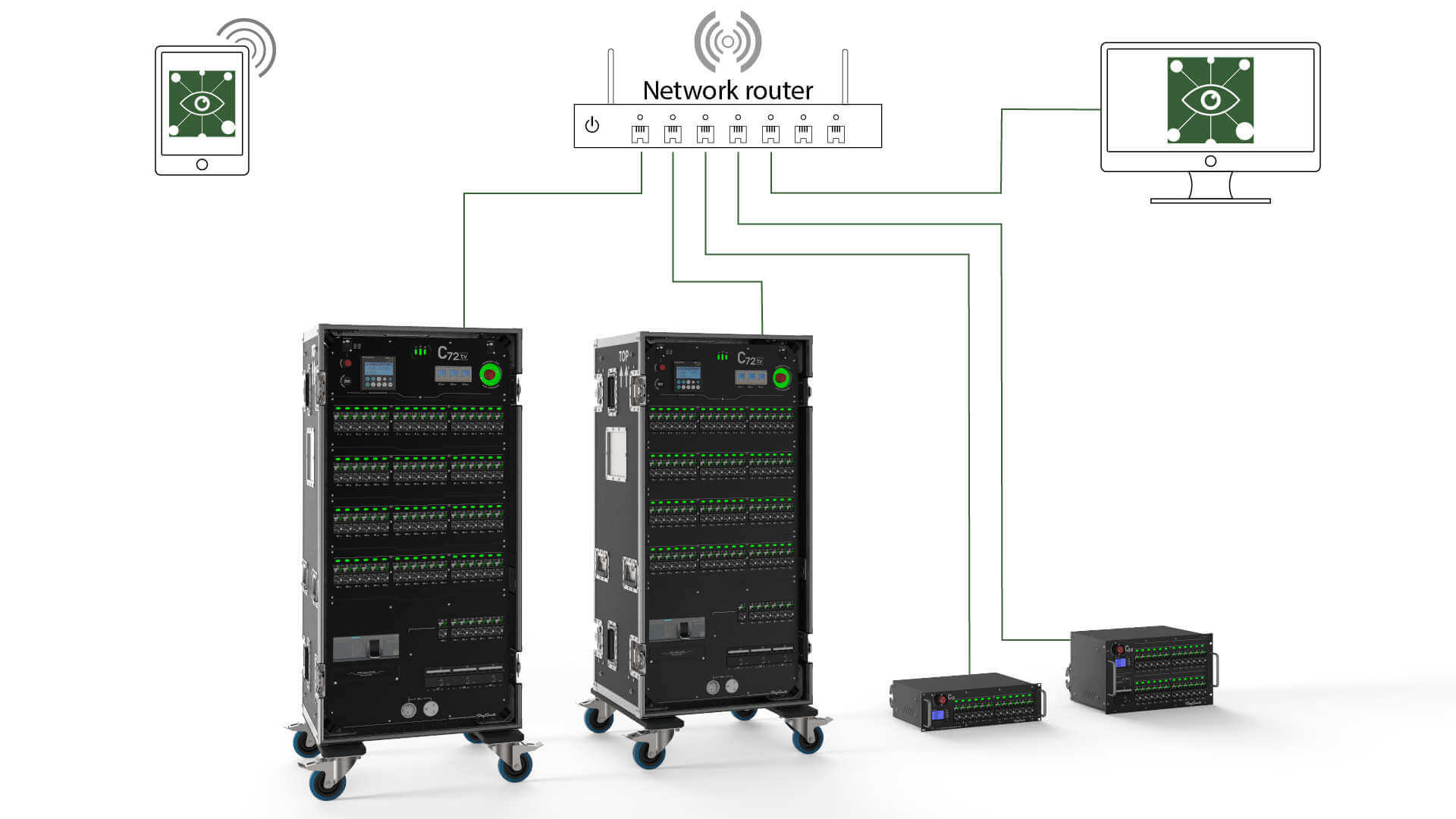
All Stage Smarts power distribution units with exception of the C-quad can have the ability to be monitored remotely over a standard ethernet network on any device with a standard web browser.
We have developed a solution that utilizes a Linux micro-computer to collect and distribute data from each unit. The internal computer communicates with all load sensors in the unit and also with the main meter to collect all relevant data about loads, voltages and so on. Furthermore, the status of the main breaker, emergency stop, neutral-protection and the internal temperature are collected and processed by the system. The integrated webserver displays the collected data in real time on a webpage that can be accessed by typing in the unique serial-number or the IP-address for each unit. All units can be connected to a standard network with other traffic being managed at the same time so there’s no need for a proprietary network.
Multiple units can be connected to a single network and you only need to access one of the units to gain access to the entire system. The connected units on a shared network will discover each other and share their data automatically. For the units to work together they need an external router to manage the network.
The Linux system is equipped with a battery back-up system that runs for approximately 10 minutes to enable you to get crucial information about the status of the unit even if your setup has lost all power.
Web client
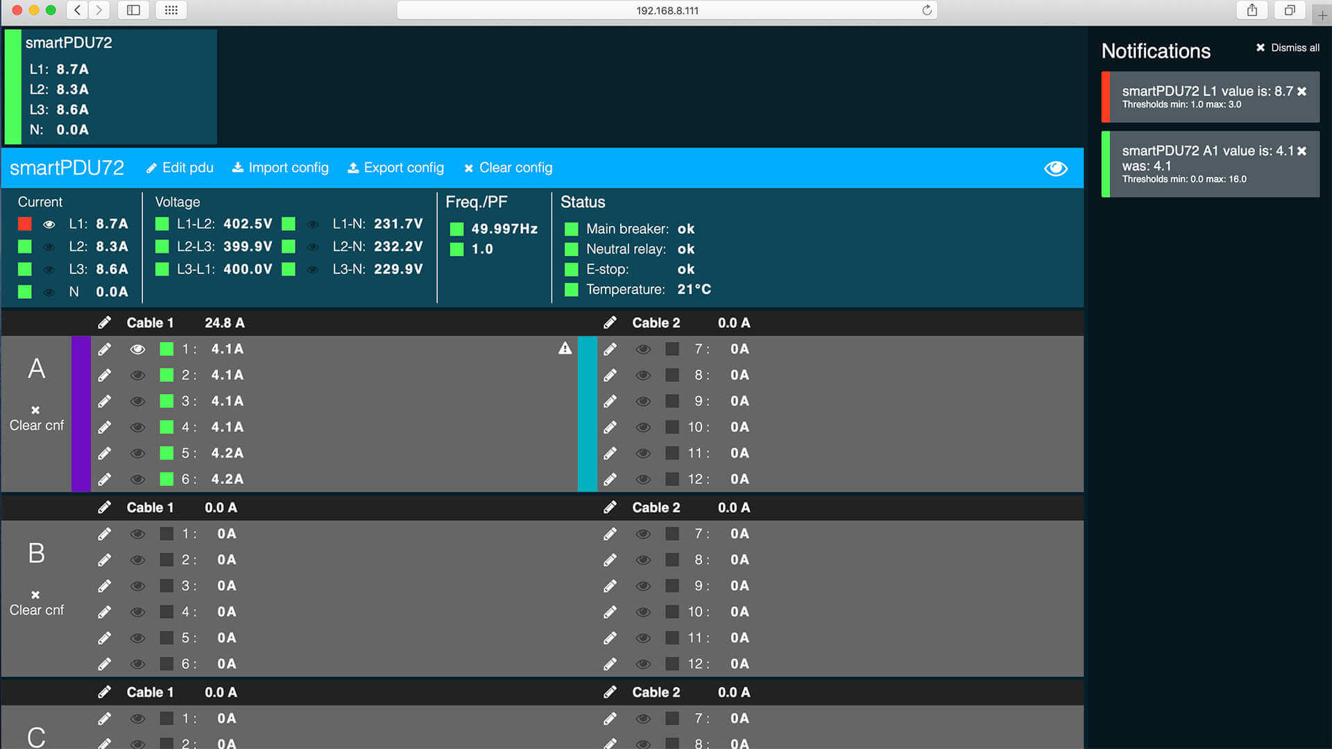
The data collected from all connected units is presented on a web page to the client connected to the network, multiple clients can view the data simultaneously on different browsers, the page is fully responsive and adapts to the client’s device.
All connected units are fixed to the top of the viewport and the status bars shows if everything is operating under normal conditions or if there is something needing your attention. Selecting any unit will display the full status in the viewport while maintaining the overview of all connected units.
The exact current for each channel can be monitored on screen in real time and the combined current for each cable (6-channel block) are also displayed.
A supervision range can be set as a minimum and maximum value for the supply and the channel data to enable you to get a warning if the measured data goes above or below the range you are expecting it to operate in. Status indicators for each channel and the main current and voltage clearly show any overloads or supervision range violations.
Overloads and violations will also be displayed in the right-hand notification window to enable you to catch temporary problems and fluctuations. Notificatios will stack up in a scrollable list that can be dismissed as a whole or on a separate basis.
The settings made to a power distribution unit are stored automatically in each unit which ensures that you always are looking at the correct data even of you have to change the device you are using to connect with.
All system settings can be imported and exported in standard XLS format for easy integration with already prepared prep-sheets. The import / export function also enables easy migration of data between units.
System settings:
- Unit name.
- Channel name.
- Cable name.
- Cable color-codes.
- Supply current L1, L2, L3, N supervision.
- Supply voltage L1-L2, L2-L3, L1-L2 supervision.
- Channel current supervision.
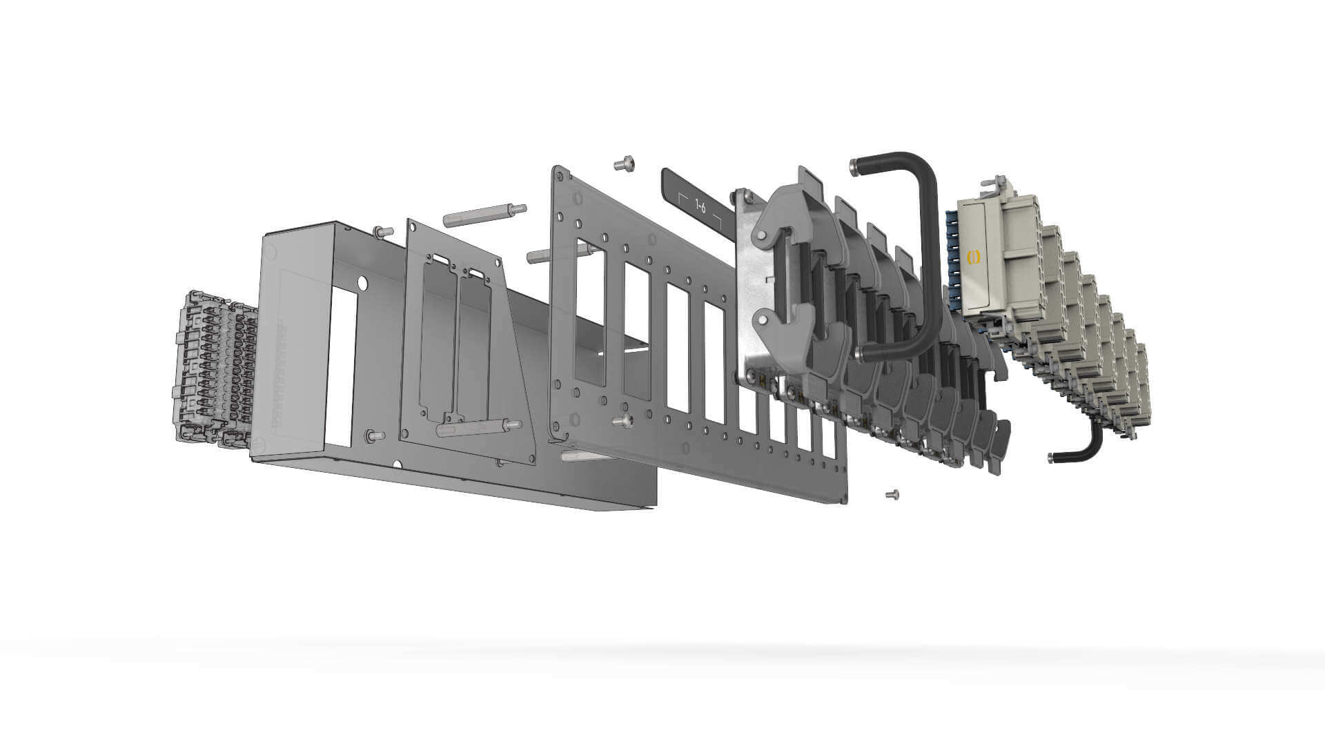
Modular outputs.
When we at Stage Smarts started to develop the smartPDU we wanted to find ways to add new functionality to the power distribution units, but we also wanted to try to add some conformity to what we believe to be kind of a scattered market.
There are a lot of different solutions out there, some good and some not so good. Problems arise when there are different connectors and wirings, sometimes even for the same type of connector which can cause possibly harmful situations if overlooked. But all of those solutions are already out there and there will most likely take a very long time before any clear and widespread standardization takes place.
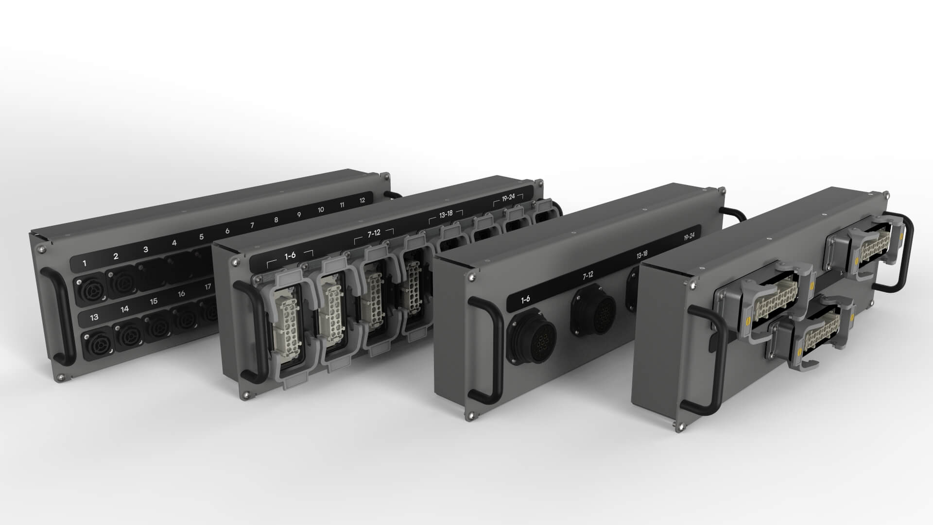
What we did was to develop the modular output, a way to quickly adapt your equipment for different markets and scenarios without having to commit to a certain design upon order. The modular design enables you to customize your units over time over and over again and also significantly raises the value for the aftermarket. It also gives you the ability to instantly fix a damaged connector on site and even during a show, switch the module for a spare one and then you send only the damaged module to the repair shop instead of decommissioning the entire unit for some time.
We have modules for many differences connectors and wiring and there is always the possibility to create something special that solves your specific problem.
- Single Soecpex, standard or Solotech wiring.
- Dual Socapex, standard or Solotech wiring.
- Single Harting 16, 6 channels, different wirings.
- Dual Harting 16, 6 channels, different wirings.
- Harting 16, 8 channels.
- Harting 24, 8 channels.
- Harting 10, 4 channels.
- Single Neutrik True1
- Dual Neutrik True1
All configurations are not available for certain products.
Durable design
We take our commitment to quality and durability very seriously when we design our products at Stage Smarts. Our goal is to create high quality products that can live with you for a long time and always perform as they were intended to.
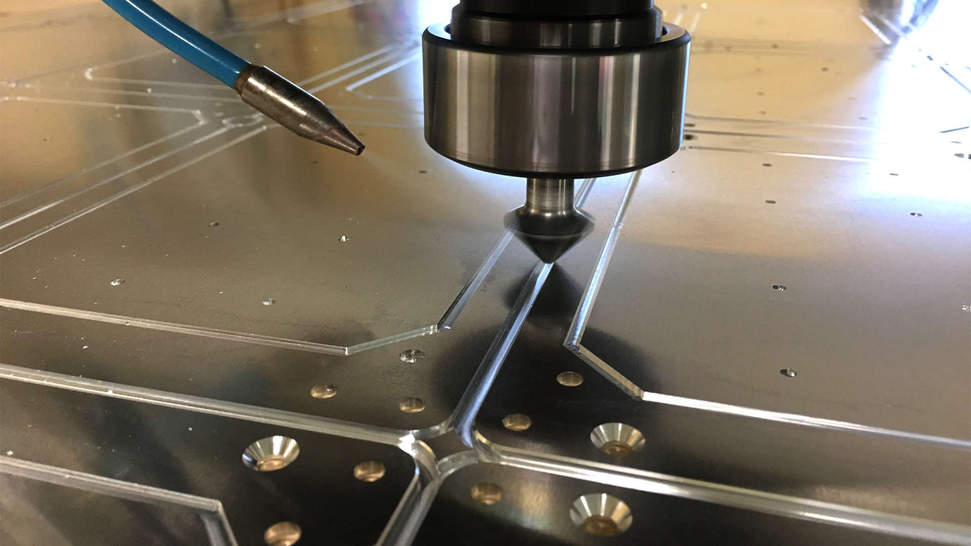
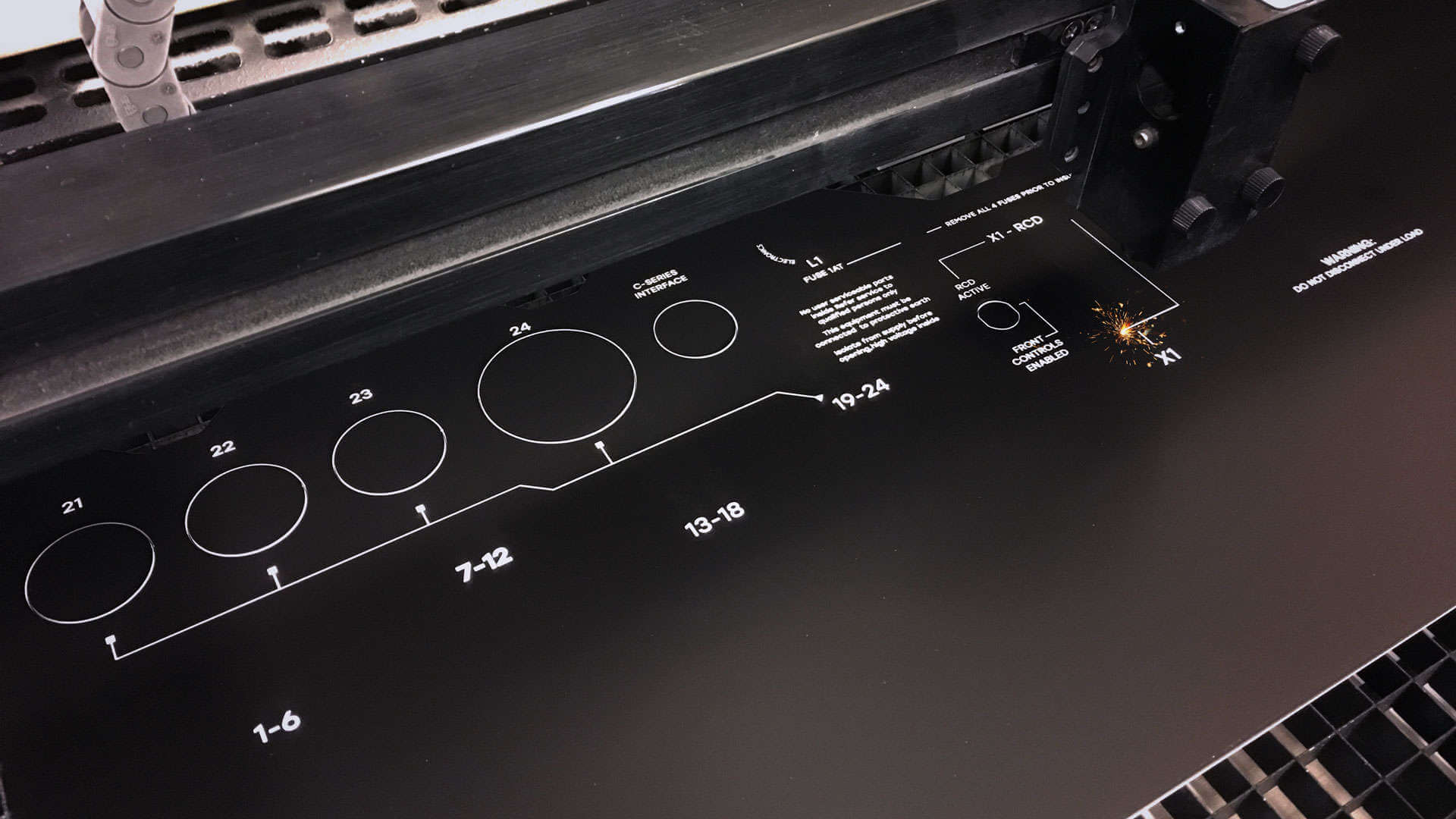
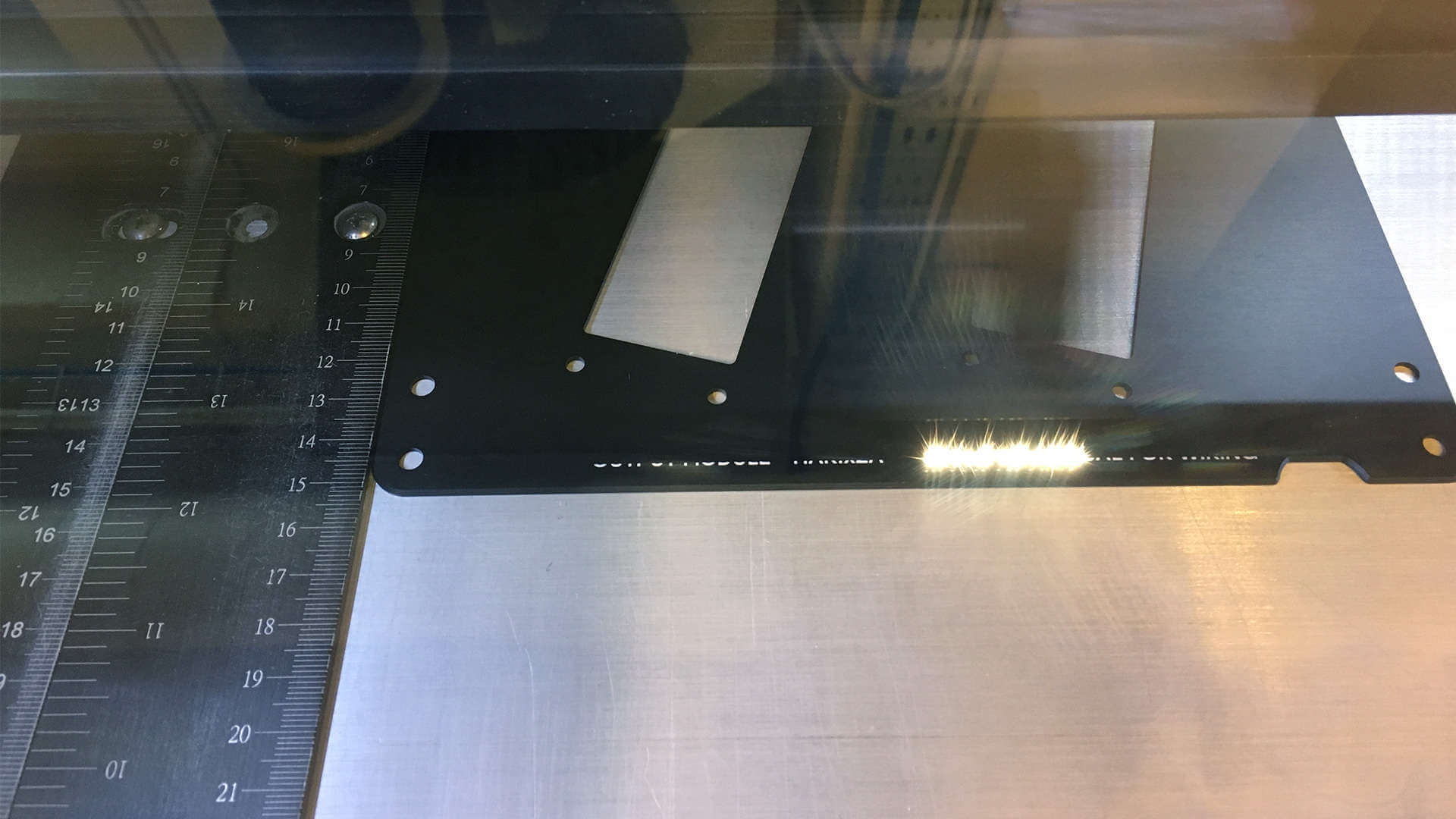
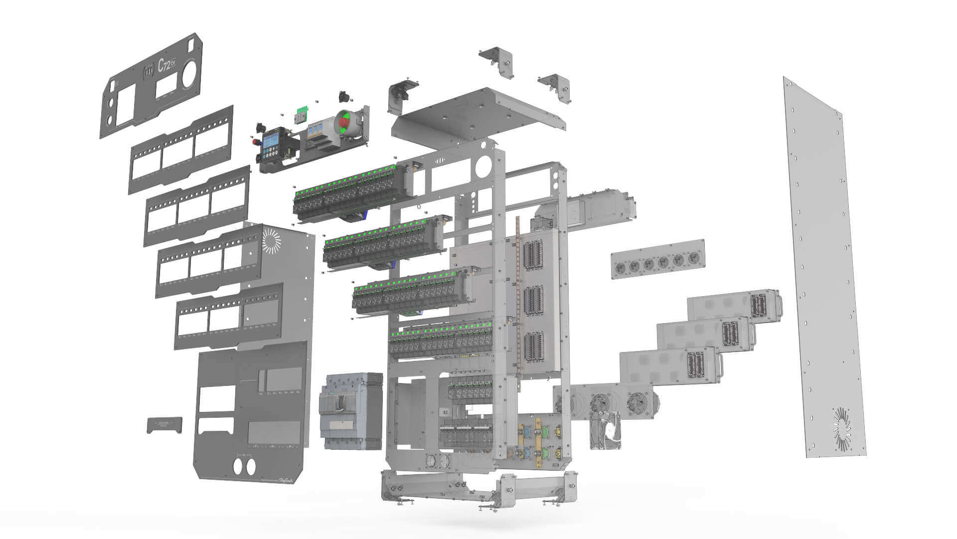
We use state of the art CAD / CAM systems to design and manufacture the mechanical parts that compromise the framework that holds everything together. The front panels are precision-routed in flat-bed CNC routers to ensure very tight tolerances and a high surface finish. The aluminum front panels are anodized to create a durable and esthetically pleasing surface and then laser-engraved in-house for a very durable and flexible marking.
The steel chassis are punched, laser-cut and bent in a CNC-controlled workflow that enables tolerances down to 2/10 of a mm for a good final fit. All steel parts are made out of corrosive resistant Aluzinc to ensure a long lifespan even for uncoated details. External and visible parts are powder-coated for a nice surface finish and even higher resistance against corrosion.
Durability, functionality, serviceability and good design are the core of what we strive for in our aim to produce a product that are greater than the sum of its parts.

